Transformer Tan Delta Test and Capacitance Test : Tan Delta Modes Demystified !
Transformer Tan Delta and Capacitance Test is carried out for Bushing, Winding and Transformer Oil.
It is carried out for Insulation assessment of the Transformer for detecting Moisture, Carbonization/Contamination and Mechanical Failure.
It is used for Comparison with the Standard Values, Change in the Test results over time (Trend) and Changes in the Test Results as a function of applied Voltage.
Permissible Limit of Tan Delta is 0.7 %
Rate of Rise is 0.1 %
Winding Tan Delta Test:
What are the Precautions to be taken before carrying out the Test ?
Answer:
1) Transformer needs to be completely isolated with Jumpers and Neutral Earthing removed.
2) Porcelain of the bushings shall be clean and dry. Remove any dirt or oil with clean dry cloth.
3) All Bushings (R, Y & B Phase) of the same Winding are to be shorted together, with the help of bare braided copper jumper.
4) Test is to be carried out in a Sunny time (Less Humidity).
5) Ambient temperature and relative humidity must be recorded for reference and Temperature Corrections.
6) Supply to the Kit should be 230 V AC and the Voltage between Neutral Point and the Earth should not be more than 5V. Also the Test Kit Ground, Test Object Earth and test Kit Supply Earth are connected to each other i.e. they are at equipotential point.
What is the Procedure for carrying out the Winding Tan Delta Test of a Three phase Two Winding Transformer ?
Answer:
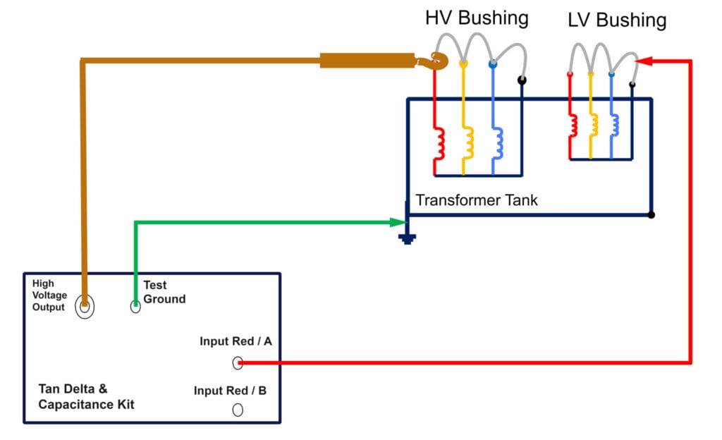
1) Connect the Test kit’s ‘High Voltage Output’ to the HV Winding and the Test kit’s Measurement ‘Input Red/ A’ to the LV Winding and the Kit’s ‘Test Ground’ to the Transformer Earth.
Run the Test for 2 KV, 5KV and 10 KV for following modes:
Test 1: HV-LV (CHL) Test Mode: UST A
Test 2: HV-E (CH) Test Mode: GSTg A+B
Test 3: HV-LV + E (CH + CHL) Test Mode: GSTg B
Check if Capacitance in Test 1 + Cap in Test 2 = Cap in Test 3
2) Connect the Test kit’s ‘High Voltage Output’ to the LV Winding and the Test kit’s Measurement ‘Input Red/ A’ to the HV Winding and the Kit’s ‘Test Ground’ to the Transformer Earth.
Run the Test for 2 KV, 5KV and 10 KV for following modes:
Test 1: LV-HV (CLH) Test Mode: UST A
Test 2: LV-E (CH) Test Mode: GSTg A+B
Test 3: LV-HV + E (CL + CLH) Test Mode: GSTg B
Check if Capacitance in Test 4 + Cap in Test 5 = Cap in Test 6
3) Enter the Test results in the Table given below:
| Sr No | Test | 2 KV | 5 KV | 10 KV | |||
| Cap (nF) | TanD | Cap (nF) | TanD | Cap (nF) | TanD | ||
| 1 | HV-LV UST A (CHL) | ||||||
| 2 | HV-E GSTg A+B (CH) | ||||||
| 3 | HV-LV+E GSTgB (CH+CHL) | ||||||
| 4 | LV-HV UST A (CLH) | ||||||
| 5 | LV-E GSTg A+B (CL) | ||||||
| 6 | LV-HV+E GSTgB (CL+CLH) | ||||||
Check if Capacitance in Test 1 + Cap in Test 2 = Cap in Test 3
Check if Capacitance in Test 1 + Cap in Test 2 = Cap in Test 3